

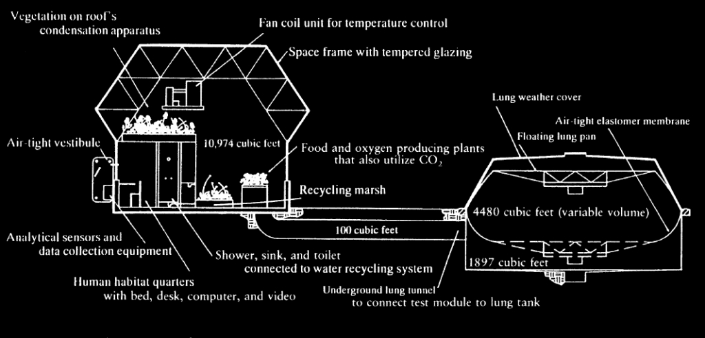
Diagram of the Test Module and Lung, circa 1987
The Test Module lung was developed as a “method of managing the effects an internal temperature and external barometric pressure change could cause in a fixed, sealed, glass structure. This problem was solved with a variable volume system joined to the module by an air duct. With increased temperature or decreased barometric pressure in the Test Module compared to the out- side environment, the variable chamber expands; with a decrease in temperature or a increase in pressure, the chamber contracts. The lung structure provides an effective means to prevent the possibility that the Test Module would implode or explode when subjected to these forces. The reservoir of air provided an increased buffering; adding approximately 20-40% to the total atmospheric volume. The weight of the pan on the lung structure insured a positive displacement from inside the closed system to the outside.” — Abigail Alling, Linda Leigh, Taber MacCallum, and Norberto Alvarez-Romo. Biosphere 2 test module experimentation program. Biological Life Support Systems 23 (1990): 32.
This week was the last, big push for resealing the Test Module and lung—dozens of small details and a few substantial undertakings before our first pressure tests on Monday.
There are 18 points at which the Test Module pressure vessel is penetrated, including the entrance and a 7-port gas exchange manifold. In the 1987-89 test runs these served various purposes: monitoring the internal air and water (drinking, waste, marsh); moving sensor data over physical cables; exchanging hot and cold water for the heat exchanger then mounted in the overhead space frame. The clean water inlet will be reainted, but used sparingly (everything that goes in, stays in). The 3″ diameter copper feeds for the heat exchanger are terminated and capped. Since the ’80s much has changed in data transmission. Now a single wireless feed can readily transmit a vast quantity of real-time data and video. However, two hard line connections (Ethernet, USB) will be installed in order to rebuild or update computers and embedded devices (e.g. WiFi router), and as a back up should the wireless go down.
As such, we have reduced the number of ports to:
- A fresh water inlet
- Wired data (Ethernet + USB)
- Electrical feeds from the external, primary panel to the internal sub-panel
- Continued use of the original, 7-port gas exchange manifold
- Two new manifolds for the mini-split heat pumps (coolant, power)
The lung is an adjacent structure connected to the Test Module by means of a 100 cubic foot, underground corridor (tube) large enough to crawl through. The lung is composed of a concrete structural frame and welded steel, cylindrical wall and floor. The upper lip of the cylinder is sealed to the larger end of the flexible rubber membrane (not unlike the rubber used on inflatable river rafts) from which is suspended a 22 foot diameter steel pan which itself is attached to the lower end of the membrane, and re-sealed (per our effort today). The area above the pan is open to the outside air. The area below the pan is an extension of the Test Module volume itself, with air movement through the restricted corridor.
The lung also has more than 20 penetrations. All but five were capped or plugged. As with the Test Module, all unused ports in the lung are sealed with Teflon tape over threaded plugs or caps.
As such, the functional ports are:
- A single feed gas manifold (may or may not be retained)
- Lung inflation fan with 3″ ball valve
- Electrical feed to lights
- Water column pressure release “P” trap
The inflated lung provides a positive pressure internal to the living space, an automated compensation for both internal temperature changes and external barometric pressure changes, and a buffer such that for the duration of a simulation, a hermetic seal may be maintained. The better the total seal, the longer a simulation can run without adding outside air.
When the Test Module and lung were inspected in the fall of 2020, it was clear that a great deal of work would be needed to regain a fully sealed function. The curved steel ring segments that held the rubber membrane in place were completely rusted from thirty years of water and weather, to the point that many of the threaded rods simply snapped off or turned to dust in one’s fingers.
Kai, Trent, and a host of volunteers have worked on various aspects of lung repair since January ’21, focused on patching the membrane itself, restoring the surface of the lower ring, welding 220 new threaded rods (studs), sealing against further rust, and then, finally, restoring the seal with a new set of individual 4″ stainless steel plates, replacing the nine heavily rusted angle iron rings segments. Furthermore, the outer shell of the lung has been completely sealed with silicone caulk and a 100% elastomeric such that only in the worst storms might a small amount of wind driven rain find its way onto the upper, external facing side of the membrane.
As of the posting of this photo essay, the silicone is a half dozen hours into a 72 hours cure. We are confident that we have a solid seal between the membrane and the lower ring of the steel pan. With the lower lung door rebuilt and ready to be installed there are no known open ports or holes in the entire pressure vessel. However, we remain aware that one or more holes may exist and that no system is fully sealed.
Our fingers are crossed for success in pressurizing the Test Module for the first time in thirty years!
Stay tuned!


